cable
MV-CABLE
Introduction
The current rating of cables is affected by the installation conditions, the cable system design and the materials and construction of the cables themselves. In this report, a parametric study of the factors which affect current ratings is presented.
For cables in air, the effect on the current rating of the following parameters is studied: conductor size, conductor material, sheath bonding arrangement, ambient air temperature, enclosing in the duct, duct size, duct material, exposure to direct solar radiation and separation between groups of cables in air.
For buried cables, the effect on the current rating of the following parameters is studied: soil dry-out, soil thermal resistivity, phase separation, standing voltage, single-core sheath loss factor, multi-core sheath loss factor, multiple buried circuits, soil ambient temperature, backfill thermal resistivity and backfill construction.
For various sheath bonding configurations, the effect on the current rating of the following parameters is studied: phase spacing for solid bonding, sheath circulating current and standing voltage, varying phase spacing along the route, and varying minor section length for solidly bonded and cross-bonded cables.
Refer to our Sheath Bonding Design for High Voltage Cables technical article.
Modelling was performed using ELEK Cable HV Software™, which uses calculations according to the IEC 60287 standards [ref. 1], equations published by Neher and McGrath, and the finite element method. The calculation results of the software have been validated with CIGRE Technical Brochure 880 [ref. 2].
Common parameters
The following common parameters were used for the modelling of the cables:
- Load factor = 1.0
- Sheath bonding = Solid
- Conductor material = Copper
- Ambient air temperature = 40 °C
- Ambient soil temperature = 25 °C
- Maximum conductor temperature = 90 °C
- Depth of burial = 0.7 metres
- Native soil thermal resistivity = 1.2 °C.m/W
- Dry soil thermal resistivity = 2.5 °C.m/W
- Dry soil critical temperature = 40 °C
- Cable sheath solar absorption coefficient, σ = 0.8
- PVC duct thermal resistance = 6 °C.m/W
- Metal duct thermal resistance = 0 °C.m/W
- Backfill thermal resistivity = 1 °C.m/W
The models for the 11 kV cables used in the parametric study are included in the Appendix.
In Air
Varying conductor sizes and conductor material
The conductor size has been varied from 35 mm2 up to 800 mm2. Cables are modelled as installed spaced from a wall in a trefoil arrangement. Below is a list of the observations from Figure 1.
-
The current rating of cables increases with conductor size.
-
Cables with copper conductors have a higher rating than those with Aluminum conductors.
-
The DC resistance of a conductor is inversely proportional to its size. However, doubling the conductor size does not double the current rating. This is because for AC currents, the contribution of the skin and proximity effects to conductor resistance, especially for large conductors, is significant.
-
Circulating and eddy currents will flow in the metal sheath for single-core cables with solid bonding. Circulating current losses are generally much larger than eddy current losses; hence, the current rating for solidly bonded cables is lower than for single-point bonded cables.
-
The larger the conductor size, the larger the circulating current losses (significant for solidly bonded cables but not applicable for single-point bonded cables) and eddy current losses.
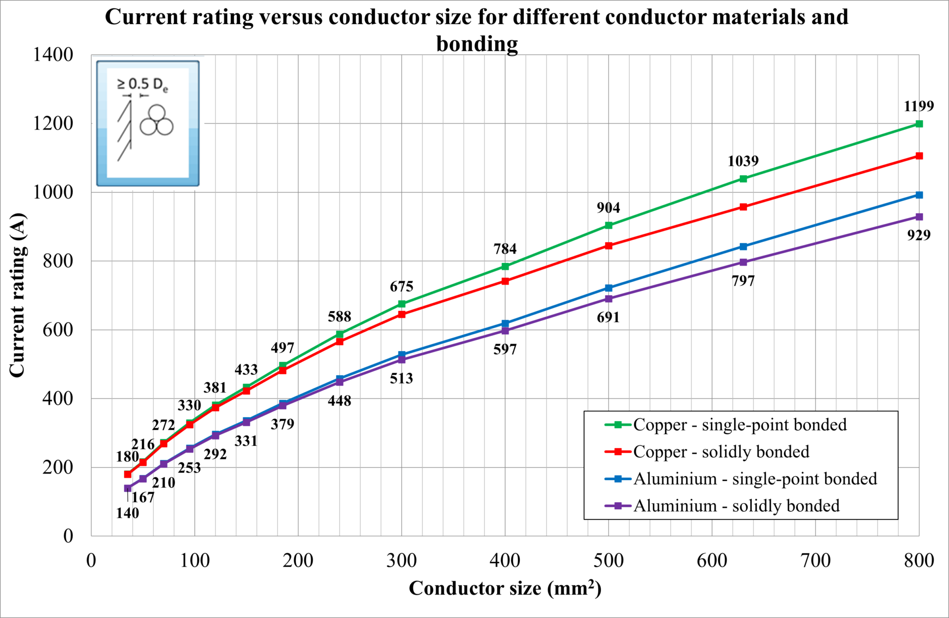
Figure 1: Current rating versus conductor size – Copper and Aluminum cables in air
Ambient air temperature
The ambient air temperature was varied between 20 ̊C and 50 ̊C for different cable sizes, and the current rating was calculated. Below is a list of the observations from Figure 2.
-
For all cables, as ambient (environment) temperature, whether air or soil, is increased nearer to the maximum conductor temperature limit, the current rating is reduced.
-
For cables in air specifically, the relationship between current rating and air temperature is a non-linear function of the excess of cable surface temperature above ambient air temperature and also depends on the outer surface area (size) of the cable – since, as can be seen, the rate of change in current rating with ambient air temperature is different for the cable sizes (diameters).
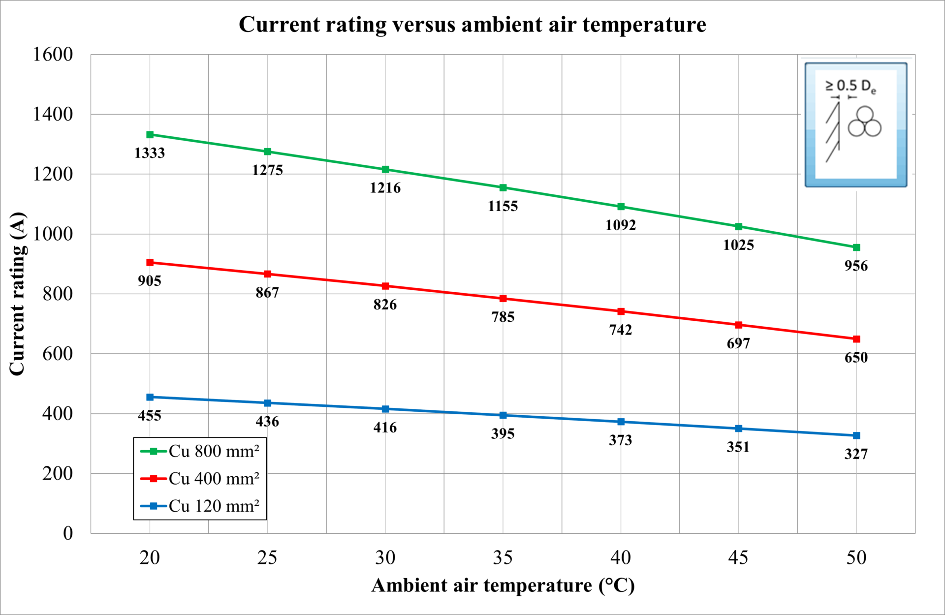
Figure 2: Current rating versus ambient air temperature
Enclosed in ducts in air
The duct size was varied for three cables enclosed (combined) in a duct, and the current rating was calculated. The duct material was also changed between PVC, which has a thermal resistivity of 6 K.m/W, and metal, which has negligible thermal resistivity. Below is a list of the observations from Figure 3.
-
The current rating of cables enclosed in ducts is reduced compared with unenclosed ones. This reduction is caused by the added thermal resistance of the duct wall and the raised temperature of the air enclosed inside the duct.
-
The duct material influences the current rating of a cable, depending on the thermal resistivity, but not very significantly because the duct wall thickness is relatively thin.
-
As the duct size increases (for the same cable size), so does the current rating. This is due to the reduced external thermal resistivity experienced by the cables, caused by the reduced temperature of the air enclosed in the duct.
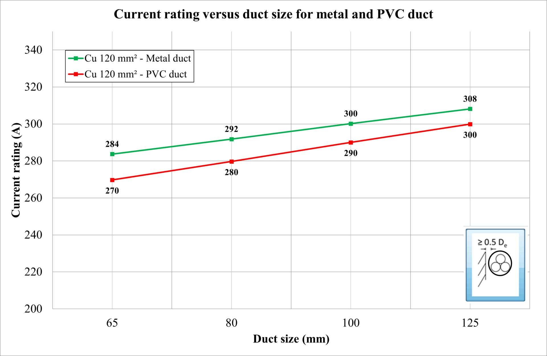
Figure 3: Current rating versus duct size – cables in air
Exposure to direct solar radiation
Cables of different sizes were modelled as exposed to direct solar radiation, and the intensity was varied from 0 W/m2 (shaded) up to 1000 W/m2. IEC 60287-3-1 states that when no information about the intensity of solar radiation is available, a value of 1000 W/m2 should be adopted. The surface absorption coefficient depends on the material type of the outer cable sheath. Below is a list of the observations from Figure 4.
-
Exposure to direct solar radiation increases the operating temperature, reducing the current rating of cables installed in the air.
-
The slope of the plots shows that the current rating is reduced more for larger (greater surface area) cables than for smaller (less surface area) cables.
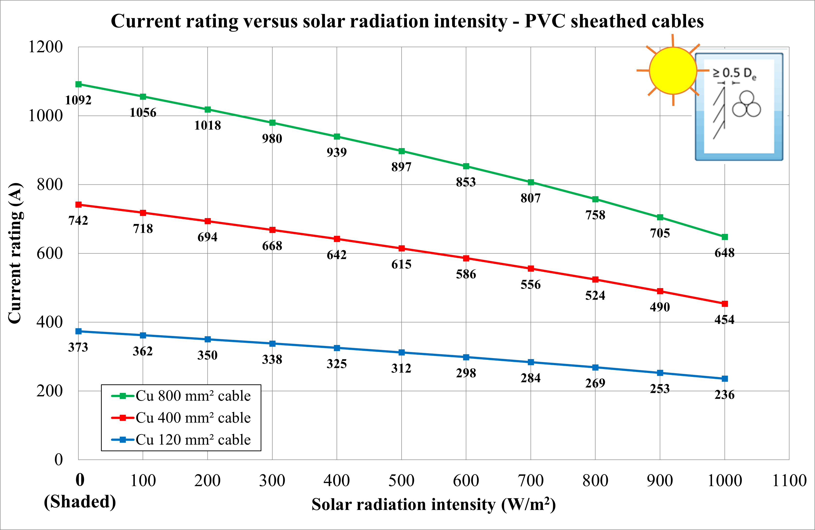
Figure 4: Current rating of 120 mm2, 400 mm2 and 800 mm2 cables exposed to varying solar radiation intensity
The angle of the surface (exposed to solar radiation)
The solar radiation intensity depends on the geographical location (latitude and longitude), the day of the year, and the hour of the day. The solar radiation intensity experienced on an angled (45 degrees), horizontal, and vertical (cable) surface was calculated for 24 hours. Below is a list of the observations from Figure 5.
-
The intensity varies throughout the day as the position of the sun changes.
-
The solar intensity is generally highest when the sun is perpendicular to the surface.
-
The maximum solar radiation intensity throughout the day is little affected by the angle of the surface.
-
The peak solar radiation intensity occurs for a vertical cable surface during sunrise and sunset.
-
The peak solar radiation intensity occurs at midday for a horizontal cable surface.
-
The peak solar radiation intensity depends on the surface angle for an angled cable surface.
-
The average solar radiation intensity is higher for an angled (45-degree) surface than the horizontal or vertical cable surface.
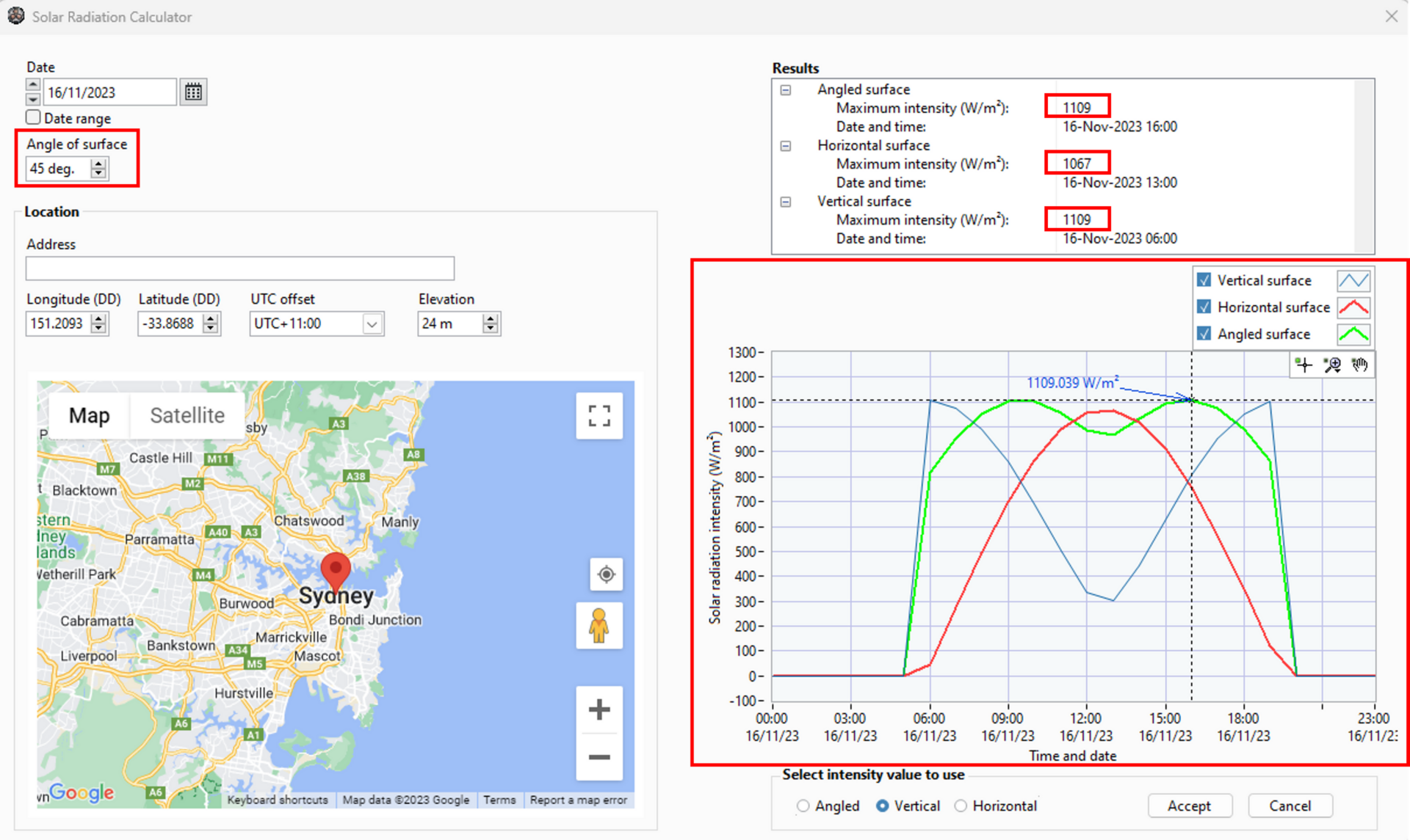
Figure 5: Solar intensity calculator
Groups of cables in air
When cables are installed in groups in the air, the rating of the hottest cable will be lower than when the same cable is installed in isolation. This reduction is caused by mutual heating. Below is a list of the observations from Figure 6.
-
The effects of grouping in the air on current ratings depend on the cable diameter (De) ratio and the separation between circuits (e).
-
If the separation between groups exceeds the critical ratio of e/De, then the thermal proximity effects, which cause the de-rating of the circuits, can be neglected.
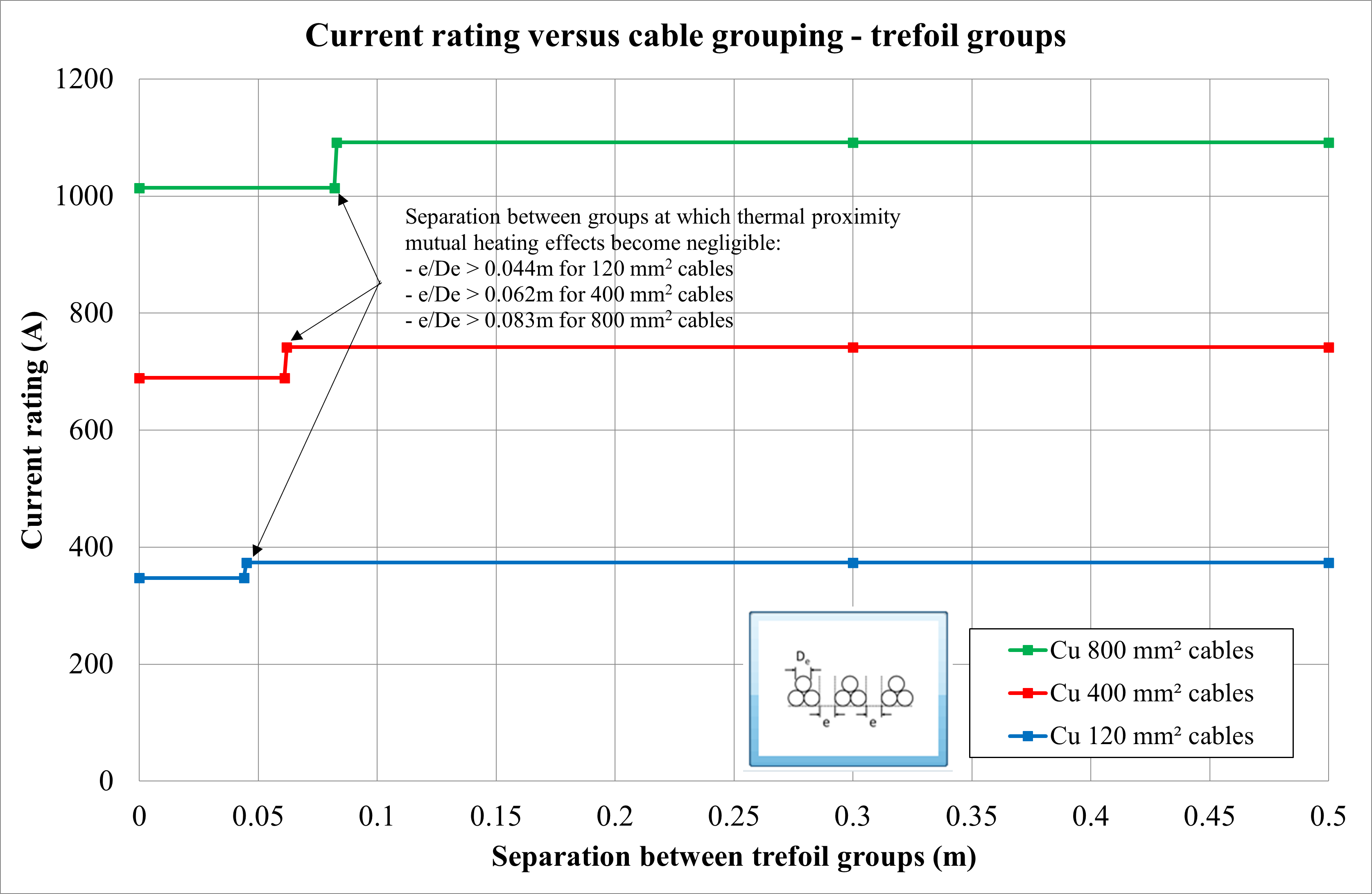
Figure 6: Current rating versus separation between trefoil groups
Buried cables
Varying conductor sizes and soil dry-out
The conductor size has been varied from 16 mm2 up to 800 mm2. Cables are modelled as directly buried in a trefoil and touching arrangement. The phenomenon of soil dry-out requires an explanation. Soil thermal resistivity is not constant and is highly dependent on soil moisture content. As soil heats up caused by the loading of the cables, moisture may tend to migrate away from the cable surface. A dried-out soil zone can develop around the cables in which the thermal resistivity is increased. This, in turn, tends to increase the cables’ temperature, reducing their ratings.
A two-zone model for the soil surrounding loaded cables addresses the complex effect of moisture migration on cable rating calculations. The concept of the model is summarised as follows. Moist (native) soil is assumed to have a uniform thermal resistivity; however, if the heat dissipated from a loaded cable and its surface temperature is raised above a certain critical temperature, then the soil immediately surrounding the cable will dry out resulting in a zone which is assumed to have a higher uniform thermal resistivity.
Below is a list of the observations from Figure 7.
-
The increase in current rating with conductor size is more non-linear, and the current ratings are lower for cables in soil compared with cables in air.
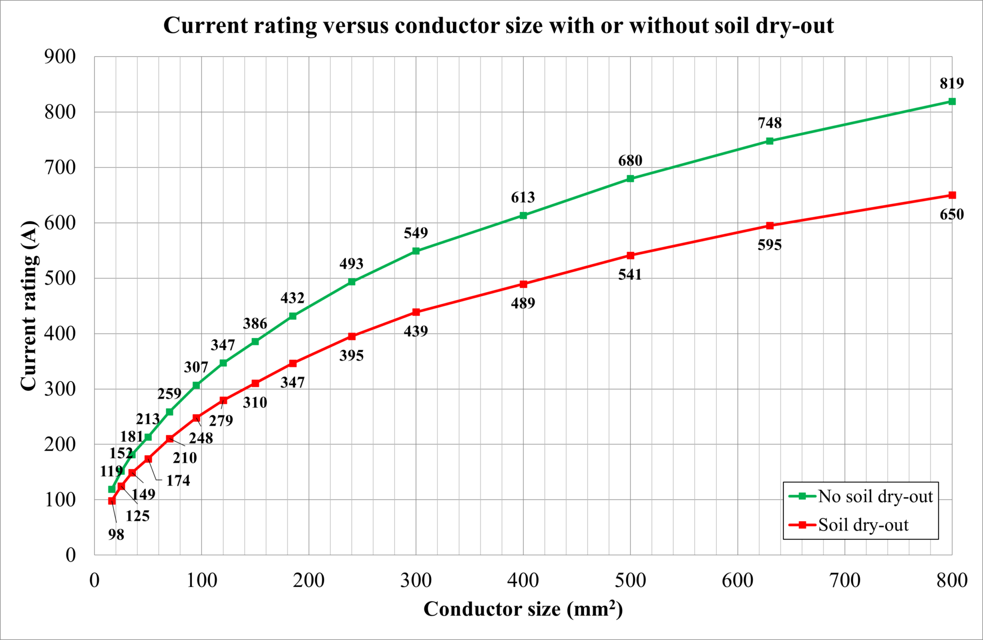
Figure 7: Current rating versus conductor size – cables direct buried
